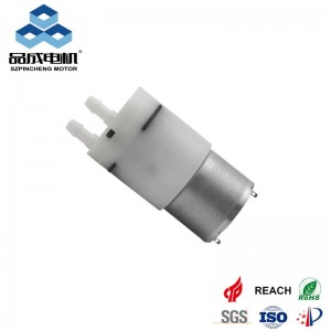
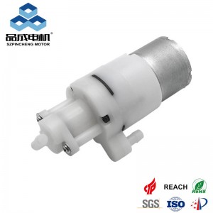
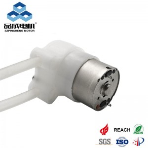
Micro water pumps supplier
Accurately measuring the flow rate and pressure performance of a micro diaphragm pump is critical for selecting the right pump for your application and ensuring its reliable operation. Unlike ideal specifications, real-world performance is influenced by numerous factors. This guide outlines the essential methods, equipment, and considerations for conducting these vital tests.
Why Accurate Testing Matters:
-
Verify Manufacturer Specifications: Ensure the pump meets its claimed performance under your specific conditions.
-
Application Suitability: Determine if the pump delivers the required flow against the actual system pressure (head loss).
-
System Integration: Understand how the pump behaves within your complete fluidic system.
-
Troubleshooting: Diagnose performance issues like reduced flow or inability to reach pressure.
-
Quality Control: Perform incoming inspection or production testing.
Essential Test Equipment:
-
Power Supply: A stable, adjustable DC or AC power supply matching the pump's voltage requirements. A multimeter to monitor voltage and current is crucial.
-
Flow Meter: Select based on expected flow range and fluid compatibility.
-
Digital Mass Flow Meters (Liquid/Gas): Highly accurate, often include totalizers.
-
Rotameters (Variable Area Flow Meters): Cost-effective, visual indication, requires calibration for specific fluid.
-
Turbine Flow Meters: Good for moderate flow rates, need clean fluid.
-
Coriolis Meters: Very accurate for mass flow, but expensive.
-
Volumetric Measurement (Graduated Cylinder & Stopwatch): Simple, low-cost method for liquids. Measures collected volume over time (
Flow Rate = Volume / Time). Accuracy depends on operator skill and cylinder precision.
-
-
Pressure Gauge(s) or Transducer(s):
-
Place one at the pump's OUTLET (
P_out). -
Place one at the pump's INLET (
P_in) if testing with significant suction lift or inlet restriction. Gauge range should exceed expected pressures.
-
-
Pressure Control / Load (DUTY Point Simulation):
-
Needle Valves: Fine control of outlet restriction to simulate system backpressure.
-
Pressure Regulators: Provide more stable pressure control.
-
Water Column (Manometer): Simple way to apply a specific backpressure for low-pressure testing (e.g.,
Hmeters of water =H* 9.8 kPa).
-
-
Tubing & Fittings: Use appropriate sizes and materials compatible with your fluid Minimize length and bends between the pump and sensors to reduce measurement errors.
-
Fluid Reservoir: Contains the test fluid. Ensure sufficient volume and appropriate fluid conditioning (temperature).
-
Data Logger (Optional but Recommended): Records voltage, current, flow, pressure over time for detailed analysis and curve generation.
Standard Test Setup:
[Fluid Reservoir] -> [Inlet Tubing] -> [Pump Inlet] -> [MICRO DIAPHRAGM PUMP] -> [Outlet Tubing]
                                                          |
                                                          V
                                                  [Pressure Gauge (P_out)]
                                                          |
                                                          V
                                       [Needle Valve / Pressure Regulator] <--- [Pressure Control]
                                                          |
                                                          V
                                                  [Flow Meter]
                                                          |
                                                          V
                                                  [Collection/Return]
Key Testing Procedures:
1. Flow Rate Test (at Constant Pressure):
-
Goal: Measure the volume of fluid delivered per unit time against a specific outlet pressure.
-
Method:
-
Prime the pump and system with the test fluid (if liquid).
-
Set the power supply to the pump's rated voltage.
-
Adjust the outlet Needle Valve or Regulator to achieve the desired target outlet pressure (
P_out), as read on the outlet pressure gauge. Record P_out. -
Allow the system to stabilize (flow and pressure become constant - may take seconds to minutes).
-
Measure the flow rate:
-
Using a Flow Meter: Read the instantaneous flow rate directly.
-
Using Volumetric Method: Start a timer simultaneously as you start collecting fluid in a graduated cylinder. Stop the timer when a sufficient volume is collected. Calculate Flow Rate = Collected Volume / Collection Time.
-
-
Record Flow Rate, P_out, Voltage, Current.
-
(Optional) Repeat steps 3-6 for different target outlet pressures to build a flow vs. pressure curve.
-
2. Pressure (or Head) Test (at Constant Flow / Shut-off):
-
Goal: Measure the maximum pressure the pump can generate at zero flow (shut-off head) or against a restriction.
-
Method:
-
Prime the pump and system.
-
Set the power supply to the pump's rated voltage.
-
For Shut-Off Head:
-
Completely close the outlet needle valve.
-
Allow pressure to build until stable (usually reaches maximum quickly). CAUTION: Ensure all components can safely handle the shut-off pressure.
-
Record the maximum
P_out(Shut-Off Pressure).
-
-
For Pressure at a Specific Flow:
-
Adjust the outlet needle valve to achieve a desired target flow rate, as read on the flow meter.
-
Allow the system to stabilize.
-
Record
P_outand the Flow Rate.
-
-
Record Voltage and Current in both cases.
-
3. Generating a Performance Curve (The Gold Standard):
-
Goal: Plot the relationship between Flow Rate (Q) and Outlet Pressure (P) at a constant voltage. This is the most valuable representation of pump performance.
-
Method:
-
Start with the outlet valve fully open (minimal backpressure, maximum flow, near zero P_out). Measure and record Q and P_out.
-
Gradually close the outlet valve in small increments.
-
At each increment, allow pressure and flow to stabilize.
-
Measure and record Q, P_out, Voltage, and Current at each stable point.
-
Continue until the valve is fully closed (Q=0, P_out = Shut-Off Pressure).
-
Plot Flow Rate (Q) on the X-axis vs. Outlet Pressure (P_out) on the Y-axis. Connect the data points to form the Q-H curve. Plot Current (I) on a secondary Y-axis if desired.
-
Critical Factors Influencing Test Results (Must Control/Monitor):
-
Voltage: Performance is highly voltage-dependent. Test at the exact specified operating voltage. Monitor voltage at the pump terminals under load.
-
Fluid Properties: Viscosity, density, and temperature significantly impact performance. Test with the actual fluid used in the application at its operating temperature. Water at 20-25°C is the standard reference fluid.
-
Inlet Conditions:
-
Suction Lift (Negative Inlet Pressure): If the pump is lifting fluid from below its inlet, measure
P_in. Performance degrades with lift. -
Inlet Restriction: Clogged filters or long/small inlet tubing reduce flow and pressure capability. Minimize inlet restrictions during testing unless specifically testing their effect.
-
-
System Backpressure: Accurately controlled and measured outlet pressure (
P_out) is key. -
Air/Vapor in Liquid Lines: Ensure the system is properly primed and purged of air bubbles, which drastically reduce performance. Self-priming ability needs specific testing protocols.
-
Pump Orientation: Some pumps may have orientation-dependent performance (check datasheet).
-
Warm-up: Some pumps (especially electromagnetic types) may change performance slightly as they reach thermal equilibrium. Note if testing "cold" vs. "warm".
-
Pump Wear: Performance can degrade over time. New pumps should be tested.
Interpreting Results & Common Pitfalls:
-
Compare to Datasheet: Plot your measured curve against the manufacturer's curve (ensure same voltage, fluid, temp).
-
Understand the Curve: Flow decreases as pressure increases. The pump operates somewhere along this curve based on the system resistance.
-
Shut-Off Pressure ≠ Working Pressure: Operating continuously at or near shut-off pressure is stressful and can shorten pump life.
-
Mismatched Equipment: Using a flow meter with too large/small a range reduces accuracy. Ensure pressure gauges have appropriate resolution.
-
Ignoring Inlet Pressure: For suction lift applications,
P_inis critical. Actual pump differential pressure isΔP = P_out - P_in. -
Leaks: Even small leaks in fittings will ruin pressure and flow measurements.
-
Unstable Readings: Allow sufficient stabilization time after each adjustment. Fluctuations can indicate air ingestion, cavitation, or system compliance.
-
Cavitation: If inlet pressure is too low (high lift, restriction), vapor bubbles form and collapse, causing noise, vibration, reduced flow/pressure, and damage. Monitor
P_inand listen for "marbles" sound.
Advanced Considerations:
-
Dynamic Response: Test how quickly the pump reaches target flow/pressure after startup or load changes.
-
Pulsation/Damping: Measure outlet pressure pulsation amplitude. Dampeners might be needed for sensitive applications.
-
Efficiency: Calculate hydraulic power (
Power_hyd = ΔP * Q) and electrical input power (Power_elec = V * I). Efficiencyη = Power_hyd / Power_elec. -
Temperature Rise: Monitor pump case temperature during extended operation at various duty points.
-
Compliance (System Volume): Air bubbles or flexible tubing act like a spring, absorbing pulsations and affecting dynamic response and apparent flow stability.
Conclusion:
Accurate testing of micro diaphragm pump flow and pressure is fundamental engineering practice. By carefully setting up the test rig using appropriate instruments, meticulously controlling key variables (especially voltage and fluid), systematically collecting data across the operating range, and critically analyzing the results (especially the Q-H curve), you gain invaluable insight into the pump's true capabilities. This knowledge ensures optimal pump selection, reliable system integration, effective troubleshooting, and ultimately, the success of your application. Always prioritize safety, especially when testing near maximum pressures.
you like also all
Read More News
Post time: Jul-09-2025


